
How are the popular energy-saving lamps, controlled by a single, fully contactless touch sensor, designed? You only need to touch a specific area of the insulating plastic casing without directly interacting with conductive parts.
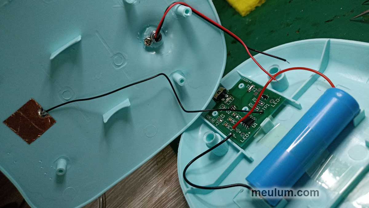
The touch sensor is a small square piece of copper foil with an attached wire. This foil is adhered under the marked sensor area of the casing.
I use similar self-adhesive foil for shielding guitar pickguards. It's a great material for making radio antennas and even large demonstration circuit boards for teaching electronics or showcasing projects.

Touching the sensor area creates a capacitor, where the fingertip acts as the upper plate and the foil as the lower plate.
The capacitance is very small but enough to detune a high-frequency oscillator. This principle is used in the theremin—one of the earliest electronic musical instruments.

In Hammond organs, a small variable capacitor is rotated by a motor, changing the resistance to AC current and thus the voltage in a divider circuit. This forms the basis of the tremolo effect.

A capacitive touch sensor works by detecting frequency changes in an oscillator or high-frequency current leakage when someone approaches the sensor plate.
Direct contact with the plate isn’t necessary, as alternating current passes through capacitors.
This principle is often used to bias transistor bases or operational amplifier inputs for amplifying AC signals.
For instance, in the BOSS OD-1 overdrive pedal, transistors Q1 and Q2 are connected to virtual ground through resistors R2 and R19, while capacitors C1 and C12 allow AC signals to pass while blocking DC.

Similarly, the non-inverting input of operational amplifier U1A receives DC bias via resistor R6 and AC signals from transistor Q1 through capacitor C2.
The input impedance of the operational amplifier is already high. However, a simple and inexpensive transistor protects the expensive operational amplifier from potential overvoltage at the pedal's input jack.
Alternatively, a pair of protective diodes could be used, as implemented in the GL3274 IC. This chip is designed to process signals from the photodiode of an infrared remote receiver and is also successfully used in ultrasonic rangefinders.

The upper diode protects the chip input from voltages exceeding the supply voltage, while the lower one prevents negative voltages below ground. Simple yet ingenious. Many solid-state guitar amplifier circuits include such diode pairs for protection.
My homemade LED tabletop lamp, like many similar models, is built on the SGL8022W IC. It is highly energy-efficient, consuming just 400 microamps during operation and 12 microamps in standby mode.
The operating voltage range is 2.4 to 5.5 volts, meaning the lamp can be powered directly by USB, a lithium battery, three 1.5V alkaline batteries, or a 4V lead-acid battery. The latter are often specifically made for flashlights.

A resistor can be connected between the first pin of the chip and ground to lower its operating frequency. This can help if the LED lamp's flickering interferes with other lights in the room, creating an unpleasant effect. In this DIY kit version, the first pin is left floating.

The second pin of the SGL8022W is used for connecting the sampling capacitor, which determines the sensor's sensitivity.
For an exposed metallic sensor, a 3.3 nF is recommended for C3. For thin plastic or acrylic casing, it takes 10nF, medium-thickness plastic—20nF, and thick plastic (up to 10mm)—47nF.
Despite the thin casing, this DIY kit includes an overkill 20nF multilayer ceramic capacitor, although the manufacturer suggests using a polyester film capacitor for better performance.
The sampling capacitor is a critical part of the circuit. Nevertheless, a standard ceramic SMD capacitor with an 0805 footprint performs well.
The fifth pin of the SGL8022W connects to the touch sensor. A short touch (less than 550 milliseconds) toggles the lamp on or off, switching the IC between working and standby modes.
A long touch adjusts brightness, operating in two of the IC's four possible modes. These modes are set during power-up when the IC reads the states of its control pins.
Pins 6 and 8 are internally pulled up to the supply voltage via built-in resistors. 1 = jumper open. 0 = jumper closed to ground.
T1 = 0, T2 = 0: A short press cycles through three brightness levels: off, half, and full. No intermediate levels.
T1 = 1, T2 = 0: A short touch turns the lamp on or off with smooth transitions.
This behavior prevents eye discomfort from abrupt lighting changes.
T1 = 1, T2 = 1: A short touch toggles the lamp, while holding the sensor smoothly adjusts brightness up and down.
T1 = 0, T2 = 1: Similar to the previous mode, but with memory for the last brightness setting. This memory resets when power is disconnected.
I chose the last mode because it’s the most versatile and functional one.

Soldering wires directly to a lithium battery isn’t ideal due to the risk of overheating. However, the creators of this DIY kit suggest just that.
Contrary to popular belief, using a lower-powered or cooler soldering iron doesn’t reduce overheating risks. You couldn't be more wrong if you think that it does.
A high-powered soldering iron with a thick tip heats the joint quickly, preventing heat from spreading to sensitive areas. A cooler or less powerful iron prolongs heating time, increasing the risk.
The IC controls LED brightness via pulse-width modulation (PWM) on the seventh pin.
The circuit uses a standard SS8050 bipolar transistor as a power switch in a common-emitter configuration. Resistor R2 ensures the transistor is off when the IC is in standby mode, while R1 limits base current.
The lamp’s lithium battery is charged using a 4054 controller. This widely used and fascinating chip deserves its own dedicated post.
Now we can adore the little tabletop lamp I've got.
The result is a compact and versatile standalone lamp, ideal for desk work and during power outages or off-grid.


