
Today, we'll explore two types of magnetic field sensors: digital and analog Hall sensors. These are used in musical keyboards, electric scooter throttles, video game joysticks, security alarms, and many other applications.
The simplest magnetic field sensor is a reed switch. It consists of two or more flexible metal plates enclosed in a sealed glass tube. The look and function of the plates are similar to the reeds in saxophones or other reed instruments, hence the name "reed switch."

Reed switches can be normally-open, normally-closed, or changeover (SPDT). Depending on the type, the contacts either attract or repel each other when subjected to an external magnetic field.
The tube is filled with nitrogen, another inert gas, or just dehumidified air, protecting the contacts from dust and oxidation. Combined with the minimal bending angle during operation, this makes reed switches reliable and durable.
However, reed switches can falsely activate under strong vibrations or even break due to their fragile glass casings.
Another drawback is significant contact bounce, which needs to be reduced using hardware (analog) or software (digital) low-pass filters.
Hall sensors, with no moving mechanical parts, do not have these issues. As their name suggests, their operation is based on the Hall effect.
From the perspective of theoretical physics, the Hall effect has several complex nuances, but its core principle is simple.
We know that an electric current in a conductor generates a magnetic field, with field lines perpendicular to the current's direction.
This field interacts with external magnetic fields, causing forces of attraction or repulsion that can move the conductor relative to the magnet.
This principle powers magnetoelectric voltmeters. The coil in these devices deflects within a permanent magnetic field, turning a pointer.

A spring's force resists the pointer's motion, so the deflection angle is proportional to the current in the coil. The pointer stabilizes where the spring's force balances the magnetic interaction force.
But where is the conductor in cathode ray tubes (CRTs)? There is a current: a focused electron beam passes through the vacuum. This ray of electrons can be easily deflected with external magnetic fields as it generates its own magnetic field.

Thus, it’s not the conductor but the charge carriers—the electrons themselves—that are deflected in a magnetic field.
When an electric current flows through a vacuum (like a cathode ray), it carries charge that accumulates on the target it strikes.
That’s why we always connect the grid of a vacuum triode to ground through a grid-leak resistor. Otherwise, a negative charge accumulates on the grid. Its electric field repels the electrons emitted by the cathode, causing the tube to shut off.

And on the second grid of a tetrode or pentode, we apply anode voltage through a resistor to create a shield between the anode and the control grid, overcoming the dynatron effect. If any of the grids are left unconnected, the tube will eventually lock up.
By deflecting the cathode ray and modulating its brightness, it’s possible to control charge accumulation in specific areas of the target screen. This principle formed the basis of the Williams-Kilburn tube memory, which was used in many early computers.

As for current in conductors and semiconductors, like in a vacuum, it also represents the movement of charge carriers—electrons and holes. And it too is deflected by an external magnetic field because it generates its own magnetic field.
In the Williams-Kilburn tube memory, reading the electric charge from the inner side of the screen required using the phenomenon of secondary electron emission. This allowed the use of just one external electrode in the form of a foil disc and a single tube signal amplifier connected to it.
In a Hall sensor, things are even simpler: an electric current passes through a semiconductor crystal, and the potential difference between electrodes on either side of the current’s direction is measured. The external magnetic field deflects the current in the semiconductor, creating this voltage.
A typical Hall sensor is usually a three-pin chip resembling a transistor. In addition to the Hall element itself, the chip contains a voltage regulator and a signal amplifier.

With a 5-volt power supply, the linear Hall sensor SS49E provides an output current of at least 1 milliampere, so its output can be directly connected to a SO-45 analog voltmeter, which has an input resistance of 1 kΩ per volt.

This setup is sufficient for an experiment demonstrating the linear dependence of the sensor’s output voltage on the intensity of the magnetic field.

If we need to connect the SS49E to an even lower-resistance load, a single NPN transistor is enough, with its base connected to the Hall sensor’s output, its collector to the positive power supply, and its emitter through a load resistor to ground.
This forms an emitter-follower circuit, which works effectively because the SS49E’s output voltage is always higher than the base-emitter voltage of a typical small-signal silicon transistor.
In addition to analog Hall sensors, which output a voltage proportional to the magnetic field’s strength, there are also digital Hall sensors. These operate on an “on-off” principle, outputting a logical zero or one depending on the magnetic field strength.

Essentially, it’s an analog Hall sensor with an added Schmitt trigger and an open-collector output.

The Schmitt trigger provides hysteresis to prevent chaotic fluctuations at the output when the magnetic field induction is near its threshold values.
One of my favorite devices, a magnetic polarity detector, is built on two digital Hall sensors (OH44E). It’s extremely helpful when working with electric guitar pickups.
A traditional magnetic polarity indicator is a small spherical neodymium magnet inside a transparent plastic tube. Its downside is that the device’s own magnetic field is quite strong and can remagnetize an Alnico pickup magnet.
An electronic indicator contains no internal magnetic field source, only reacting to external fields, and is therefore completely safe for vintage pickups.
The device’s circuit includes two identical units, differing only in that one Hall sensor is turned face down and the other face up.
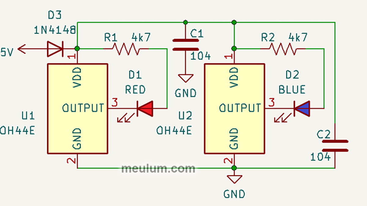
If the indicator is brought to the north pole of a magnet, a blue LED lights up, and if to the south pole, a red LED lights up.

You can see the operation of analog and digital Hall sensors, as well as the assembly process of an electronic magnetic polarity detector, in the video below:


