If you aspire to construct a custom fitness tracker or a "magic wand" that recognizes gestures, an accelerometer is indispensable. Despite its intricate nomenclature, utilizing one is remarkably straightforward.

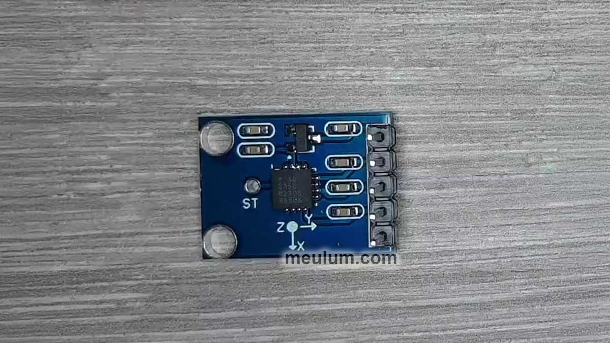
The ADXL335 accelerometer resembles a microcontroller or any other standard chip; however, within its plastic casing lies a sophisticated 3-axis acceleration sensor. How is such complexity achieved in such a compact form?
Atop a silicon wafer, there exists a polysilicon surface-micromachined structure suspended by delicate polysilicon springs. When the accelerometer experiences acceleration, this minuscule mass shifts, either stretching or compressing the springs.
The moving mass is coated in metal, forming movable capacitor plates that are ensconced between fixed plates. These fixed plates are activated by high-frequency rectangular waves of opposing polarities.
In the absence of acceleration, the moving mass—and consequently, the movable plates—are perfectly centered between the fixed plates, resulting in a potential of zero across the movable plates.
When the movable plate shifts in relation to the fixed one, a potential difference is detected by a phase-sensitive demodulator. This process creates a highly sensitive and precise sensor capable of detecting accelerations within the range of ±3.6 g.

The bandwidth range for the X and Y axes spans from 0.5 Hz to 1600 Hz, while for the Z axis, it extends from 0.5 Hz to 550 Hz. Taking into account the nominal output resistance of 32 kΩ, we can establish the desired bandwidth by connecting a capacitor of specific capacitance to the accelerometer’s output.

As a device characterized by a suspended movable mass, the accelerometer naturally responds not only to acceleration but also to Earth's gravitational pull. This factor must be considered in devices that gauge absolute acceleration values. However, today, we will focus on constructing a step counter that solely counts pulses based on fluctuations in acceleration along one axis.

We have connected a 0.01 μF capacitor (C2) to the X-axis output of our accelerometer. According to the provided table, this corresponds to a bandwidth of 500 Hz. Although this is fairly high for a pedometer, let us refrain from hasty conclusions.

The operational amplifier U1A serves as a buffer for a virtual ground. The inverting input of U1A is linked to the output, creating a negative feedback loop.
In closed-loop mode, the operational amplifier adjusts its output voltage to maintain equal voltages at both inputs. Consequently, the output voltage of U1A will correspond to the voltage at its non-inverting input, thus forming a voltage follower.
The buffered virtual ground voltage will equal half of the supply voltage, specifically 2.5 V, as two equal resistors, R1 and R2, evenly split the supply voltage.
At first glance, the configuration of the operational amplifier U1B may appear complex, but it is, in fact, quite straightforward. Remember the second rule of an ideal operational amplifier: its input impedance is so high that the input currents are negligible and can often be disregarded.
The gain of the operational amplifier U1B in non-inverting mode is determined by the ratio of resistors R6 and R7. It equals 1 + R7/R6 = 1 + 3.9 = 4.9. The voltage at the midpoint of the R3R4 divider equals the virtual ground potential divided by 4.9. Thus, in the absence of any signal at the X-axis input, the output voltage of U1B will be 4.9 * Vref / 4.9 = Vref = 2.5 V.
Take note: this is a classic method for applying an offset to a non-inverting amplifier. We feed DC voltage into the input that we wish to see at the output when there is no input signal, divided by the gain factor. In simpler terms, R7 = R3 and R6 = R4, or, more generally, R7/R6 = R3/R4.
What, then, is the purpose of resistor R5? It establishes the input impedance of the non-inverting amplifier. The output impedance of the offset divider is calculated as 1/(1/R3 + 1/R4) = 796 Ω. This is 415 times smaller than the resistance of R5, thereby allowing us to neglect it and assume that the input impedance of our non-inverting amplifier is 330 kΩ.
The output resistance of the accelerometer is also known: it is 32 kΩ. Therefore, the gain for the AC signal from the accelerometer will be 4.9 * 330 / (330 + 32) = 4.47.
The equation for the output voltage of the operational amplifier is 4.47 * Vin + Vref. However, we must remember that the 32 kΩ output resistance resides within the accelerometer, so with respect to the X-axis input, the equation appears as 4.9 * Vx-axis + Vref.
The capacitor C1 permits AC signals to pass through while blocking DC. Thus, our amplifier amplifies only the voltage fluctuations from the accelerometer, not its absolute value.
Next is a voltage follower utilizing operational amplifier U2A. Its output will also reflect the same offset Vref, as its non-inverting input is connected to the output of U1B through two resistors, R8 and R9, in series.
Why are these resistors necessary? They, along with capacitors C4 and C5, form an active Sallen-Key second-order low-pass filter with a cutoff frequency of 7.23 Hz. Even during a brisk run, it is unlikely that we would take more than seven steps per second. Thus, this provides an adequate bandwidth for a pedometer.
The final stage of signal processing involves the operational amplifier U2B. Should R11 and R10 form a negative feedback divider, the gain would be 1 + 8200 / 510 = 16.
However, let us examine this more closely. The voltage divider connects not to the inverting input but to the non-inverting input. Is this an error? No, it is not. It functions as a comparator with hysteresis. When the output voltage of the comparator is high, the potential of the non-inverting input U2B exceeds Vref, and when it is low, it falls below Vref.
This creates a "hysteresis step" that prevents false triggering. Thus, the complex waveform signal, reflecting the accelerometer’s experienced acceleration, is transformed into clock pulses suitable for a counter.

This is a basic two-digit decimal counter equipped with a seven-segment LED display. We have previously constructed similar circuits.
The video linked below demonstrates how our circuit responds to various movements of the board. As you can observe, it does not register movements that are excessively rapid or too faint. This is precisely how a step counter should operate.


