
Soil-drying sensors—or, conversely, sensors that indicate it’s time to change a diaper in a baby’s crib—alarms that detect water getting into electronic devices, and sensors in systems that close a car sunroof at the first raindrops: all of these are resistive moisture sensors.
Such electronic sensors are used everywhere, because they are truly essential. Automatic moisture sensors make our lives easier and safer. Today, we’ll take a look at how they work.
It would seem: what could be simpler? You just need to make two contacts that are shorted by a drop of water when it lands on them.
Most often, such contacts are made as zigzag parallel traces on a printed circuit board (PCB). Our test setup today is no exception.
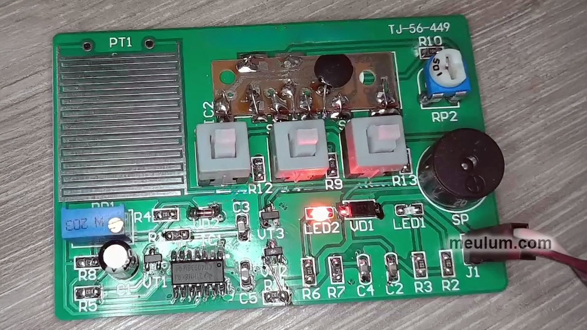
Of course, this pair of traces must be exposed, not covered with conformal coating or solder mask. To protect the copper foil from corrosion, high-end devices plate it with gold; however, ordinary tin-based solder will also do.
Tin is non-toxic and protects food-can tinplate from corrosion; however, this metal by itself is not only relatively expensive, but also brittle, and it also tends to form “tin whiskers”—microscopic threadlike crystals that can lead to short circuits in electronic equipment.
Therefore, to obtain solder, tin is alloyed with other metals. Traditionally, the first of them was lead—cheap and ductile but, unfortunately, highly toxic. Low-cost technical solders may contain 70% lead or even more.
The best solder for electronics contained 60%–63% tin, with the rest being lead. For prototyping, I still use such solders because they are high quality, low-melting, and convenient to work with.
However, end-of-life boards that contain lead must not be thrown out with household trash. They must be sent for recycling to certified e-waste recyclers. For this purpose, specialized containers are installed in many communities.

When unnecessary plastic, metal, and electronic scrap accumulate in my home and I don’t expect to reuse them, I take it to a collection point and receive a small boost to the family budget.
Depending on the application, it is very desirable—or strictly mandatory—that the solder be non-toxic and environmentally friendly. For this, it must be lead-free or at least contain very little lead.
In some countries, an alloy consisting of 90% tin and 10% lead is still used for soldering food utensils and medical equipment. However, modern standards require replacing lead in medical solders with silver and even gold.
In fact, gold-plated contacts on PCBs and connectors are not especially expensive, because the layer of precious metal applied is extremely thin.
In any case, the sensor’s signal still has to be processed. Reacting to changes in soil or fabric moisture is very easy, because soil and biological fluids contain salts that make water electrically conductive.
You only need a comparator or a Schmitt trigger that will sense the change in the sensor’s DC resistance. We have separate articles about comparators and Schmitt triggers. They are excellent devices, and I encourage you to get familiar with them if you haven’t already.
With raindrops, things are somewhat more complicated. After all, what falls from the sky is close to distilled water, condensed when water vapor cools in clouds. And chemically pure water has very high resistivity.

Of course, raindrops contain dissolved carbonic acid (H₂CO₃) and other acids formed from anhydrides present in the air. In addition, the air contains dust that includes salts which dissociate in water and cause ionic conductivity.
So, rainwater isn’t chemically pure. However, its resistance is still high. Therefore, raindrop sensors are powered not by DC but by AC, which makes them more sensitive.
Our test setup uses a nice circuit block: a multivibrator built around a single inverting Schmitt trigger. This is one of the simplest ways to build an AC voltage generator.
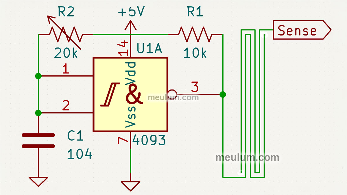
The Schmitt triggers in the IC used here are dual-input and implement a NAND logic gate. Today we just need inverters, so we connect both inputs of each of the four gates together.
A relaxation oscillator based on an inverting Schmitt trigger works as follows. The output of trigger U1A is connected to its input through a resistor. In our case, these are resistor R1 and variable resistor R2 connected in series.
Through these resistors, depending on the logic level at the output of U1A, capacitor C1 is charged or discharged.
As soon as it charges to a logic one, the inverting Schmitt trigger will switch to a low output level, and the capacitor will discharge to a logic zero, which will switch the output of U1A to one.
These relaxation oscillations will continue indefinitely as long as power is applied to the circuit. Thus we obtained a continuous oscillator using an inverting Schmitt trigger, a resistor, and a capacitor.
With variable resistor R2 you can adjust the oscillation frequency, which sets the sensitivity of our sensor.
From the sensor’s output contact, the signal goes to a non-inverting amplifier consisting of two inverting Schmitt triggers U1B and U1C connected in series.
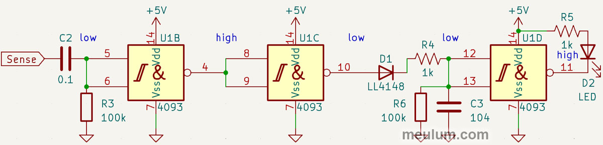
Capacitor C2 and resistor R3 form a high-pass filter that blocks DC voltage and low-frequency interference from reaching the preamplifier input.
Next, the amplified signal goes to a detector arranged exactly like in a radio receiver. Diode D1 serves as a half-wave rectifier, and resistor R4 and capacitor C3 form a low-pass filter that functions as the detector’s integrator.
In the absence of a signal from the sensor, the input of U1B is pulled to ground by resistor R3. Accordingly, it will have a logic one there, and a logic zero at the output.
At the output of inverter U1C there will be a low voltage level. Additionally, the input of U1D is pulled to ground by resistor R6, through which capacitor C3 discharges after the sensor signal disappears.
So, when there’s no input signal, the output of U1D is high, and LED D2 is off. But if a weak AC current from the relaxation generator reaches the input of U1B through a drop of water, then the signal will be detected.
C3 will charge through D1 and R4 and will remain charged as long as water is present on the sensor surface. U1D will switch to a logic zero at the output, and LED D2 will light.
Next, the raindrop detector output signal can be fed to any digital electronics and various actuators. For example, it can automatically close a car’s sunroof.
To keep today’s experiment from being boring, we used a KD9561 sound effects IC—used in security and fire alarms, as well as children’s toys—as a rain indicator.
Depending on the logic levels at three control inputs, the chip can imitate the sounds of a car engine, two types of sirens, and a machine gun.
The frequency of the built-in clock generator of the KD9561 can be changed using a trimmer resistor, resulting in a wide variety of sounds, all the way up to birdsong and science-fiction effects that depict robot signals and spacecraft noise.
In the context of my hobby of homemade analog synthesizers and pedals for electric guitars, I really love such sound chips.
If you modulate their clock frequency with an LFO and pass the output signal through a resonant filter, the result is remarkable. But these experiments deserve at least a separate article.


