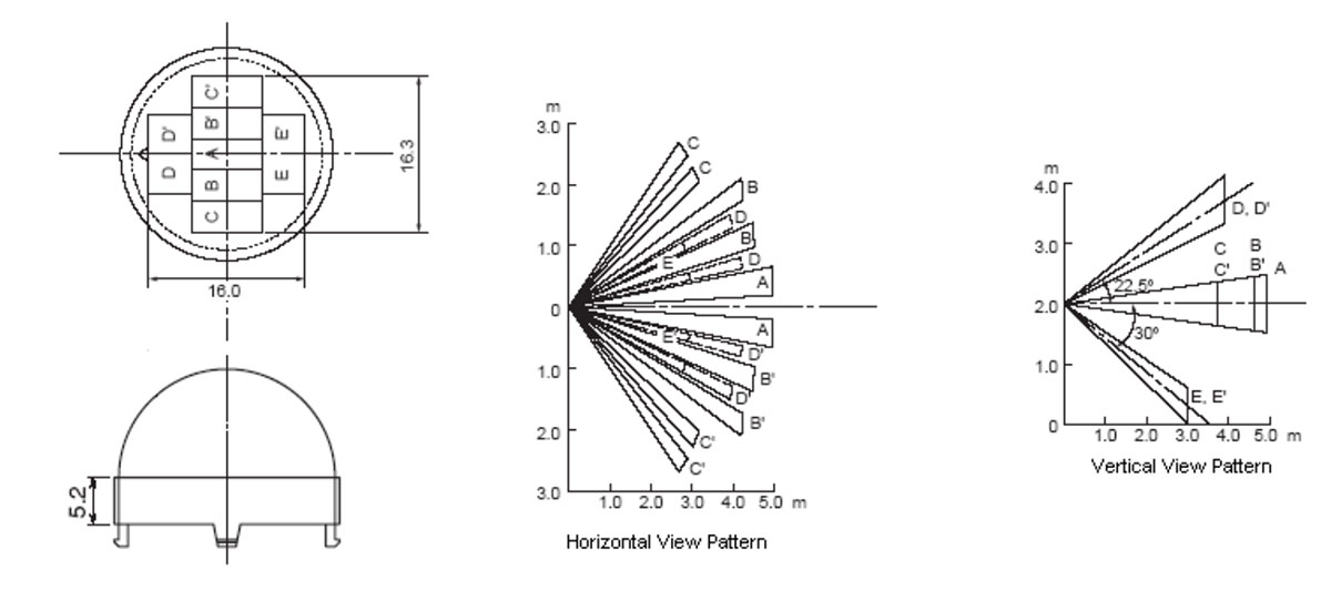
Nowadays, motion sensors are popular not only for security but also for controlling lighting and climate. I'll explain how they work and how to connect them to a microcontroller or other device.

That domed piece of white plastic looks like an igloo built from ice blocks, right?
What looks like hexagonal blocks are actually Fresnel lenses. Originally, they were invented for lighthouses. Making such a large lens in a traditional shape, like those used in glasses or microscopes, would be incredibly challenging and costly.
Moreover, a traditional lens for a lighthouse would be hefty. If mounted vertically, it could even collapse under its own weight.
Thankfully, Fresnel lenses offered a lightweight, affordable solution that was appealing not only to lighthouse builders but also to portable lights and vehicle headlights.

In a motion sensor, Fresnel lenses are arranged in a specific pattern. This design divides a room into sectors, and each lens projects the infrared light from its sector onto one-half of the sensor's sensitive element.

Infrared light refers to a region of the electromagnetic spectrum with wavelengths longer than visible light but shorter than microwaves, which we use to cook food.

Most importantly, infrared rays are heat rays. All objects and living beings emit and reflect heat. Likewise, heat rays can warm up objects; this is the idea behind infrared heaters.

If there's no movement in the room, both halves of the sensor's sensitive element are exposed to infrared rays roughly equally. However, the motion of a large object or person will unevenly change the infrared exposure on the sensor's halves.
The two halves of the sensitive element are connected in opposite phases. A JFET transistor amplifies the difference in the generated voltage.

Sensitive elements in common inexpensive sensors are usually made from pyroelectrics—materials that generate an electric voltage when heated or cooled.
Even with the built-in JFET transistor, the signal from a pyroelectric motion sensor is very weak. That's why the sensor is encased in a can-like shielded metal case, much like the vintage germanium transistors we love to use in building fuzz pedals for electric guitars.
This device is called a passive infrared (PIR) sensor because it doesn't contain an infrared light source of its own; it only detects the infrared rays generated and reflected by objects in the room.
We need two operational amplifiers and two comparators to implement a typical PIR sensor signal processing circuit.

Remember how we used operational amplifiers as comparators in an electronic thermometer?

The LM324 chip contains four operational amplifiers, so just one will be enough for our PIR sensor module!

The U1-A operational amplifier is used in a non-inverting configuration: the input signal from the JFET source goes through resistor R2 to the non-inverting input. Capacitors C1, C2, and C30 filter out high-frequency interference.
Note that U1-A's inverting input and output are not connected to any external DC circuits. It is not a DC amplifier; it amplifies pulses from the pyroelectric sensor.
We've seen similar amplification stages in guitar pedals, though they usually have a coupling capacitor on both the input and output.
The gain factor is 1 + R3/R4 = 1 + 1,000/47 = 22.3.
The RC time constant R4C4 is 2.2 seconds, meaning our sensor will not react to overly slow changes in the room's heat distribution.
The non-inverting input of the second amplifier is connected to a voltage divider R7R5, setting the reference voltage.
Notice that this reference is not half of the supply voltage, as we're used to seeing in guitar pedals; instead, it's 100/250 = 0.4 of the supply voltage, which is 5.1 volts thanks to the Zener diode ZD1 acting as a parametric stabilizer. This results in 2.4 volts.
The second amplifier's inverting input is connected to the output of the first amplifier through resistor R5 and capacitor C5.
The gain factor here is -R11/R5 = -2,700/15 = 180. That's a very high gain, and if we also multiply it by the gain of the first amplifier, the sensor pulse is amplified 4,000 times! One millivolt becomes four volts!
Afterward, a window comparator follows, consisting of two comparators, U1-C and U1-D, with reference voltages set by the divider R12R13R14.
The reference voltage of U1-C is 5.1 * 10 / (18 + 18 + 10) = 51/46 = 1.1 V. For U1-D, it’s 5.1 * (18 + 10) / (18 + 18 + 10) = 142.8/46 = 3.1 V.
When the PIR sensor's output voltage is within the 1.1 to 3.1-volt window, both comparators remain in a low logic state at their outputs. That's why such a dual comparator is called a window comparator.
As soon as U1-B's output voltage falls below 1.1 V, U1-C's output rises to a high state. The same happens with U1-D when the voltage exceeds 3.1 V.
Diodes D1 and D2 form a logical OR gate. When either comparator is triggered, the corresponding diode opens, a high logic level goes to the base of transistor Q1, and the transistor turns on, activating the relay.
Diode D3 protects the transistor from damage due to the self-induction pulse from the relay coil.
It's even better to use the BISS0001 chip, which is specifically designed for PIR sensors, instead of the quad operational amplifier LM324.

In addition to the two operational amplifiers and two comparators, this chip includes a daytime disabling function implemented via photodiode R3.
Adjusting R10 and C6 allows us to set the duration for which the relay stays on after each sensor trigger. Resistor R9 and capacitor C7 define the minimum interval before the next trigger.
The position of switch SW1 determines whether the alarm signal can be re-triggered. When SW1 is up, triggering the sensor while the alarm is active will extend the alarm duration.
If the switch is down, the chip will wait for the set interval before processing the next sensor trigger.


