Electronic devices generate heat during operation, and cooling is typically incorporated into their design. However, even efficient cooling systems don’t always do the job.
That’s why many devices benefit from additional protection with feedback control, which monitors temperature at specific points and either disables certain functions or reduces power output until the device cools down. The protection circuit also signals overheating using visual, audible, or digital alerts.
This is a truly serious issue. We might think we've accounted for everything - even overengineered it. During initial startup, a new device's temperature may not differ much from room temperature, making it seem like cooling isn't a concern. But over time, things can change.
Most thermal pastes and interfaces gradually degrade - they dry out, crack, and impair heat transfer. Household dust accumulating on heat sinks has a similar effect.

A built-in fan can seize, either partially or completely, disrupting airflow over the circuit boards and heat sinks. This usually results from clogging or bearing wear. We may sometimes detect this through changes in fan noise, but not always.
Overvoltage or undervoltage reduces power supply regulator efficiency, which can also lead to overheating - a common issue with switching power supplies in older TVs.

Or it could simply be an unusually hot day, or someone installs the device inside furniture where ventilation openings are blocked - or even a cat curls up on the warm surface. They love that.

There are countless causes of overheating in electronics, and the consequences can be severe - from minor malfunctions to complete failure, and even fire.

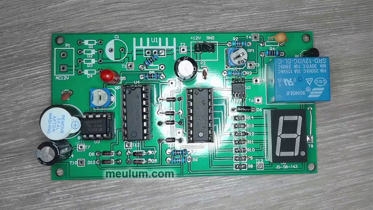
Today, we’ll build and examine a demo model of a digital device with automatic overheat protection.
The clock generator in our circuit uses the classic 555 timer IC in a standard configuration. The timing capacitor, C4, charges from a +12-volt power source through resistors R2 and R1.
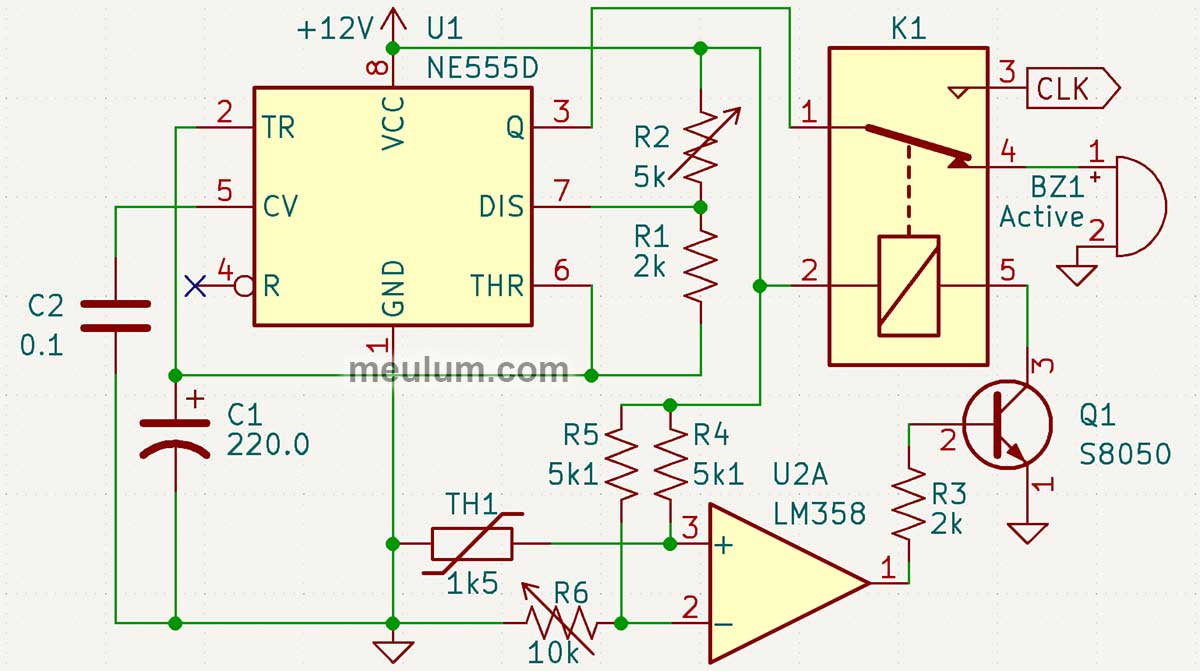
Once the voltage reaches eight volts (two-thirds of the supply voltage), the timer’s comparator triggers, and the internal flip-flop sets output Q to low.
At the same time, the internal discharge transistor - connected to the DIS pin - opens, and the capacitor begins to discharge through R1.
When the voltage drops to four volts (one-third of the supply voltage), the second comparator resets the flip-flop, setting the 555’s output to high.
The discharge transistor turns off, and capacitor C1 begins charging again until it reaches eight volts. Then, the cycle repeats. The trimmer resistor R2 allows you to adjust the oscillation period of this relaxation oscillator.
The overheat protection module is also built around a comparator - in this case, an LM358 op-amp.
U1A operates in an open-loop configuration, where the output is either high or low depending on which input has the higher voltage.
The inverting input gets a reference voltage from a voltage divider (R5 and adjustable resistor R6).
While the voltage on the non-inverting input of U2A is below the comparator threshold, the output stays low, transistor Q1 remains off, and the clock signal (CLK) passes to the digital circuit.
Thermistor TH1 has a positive temperature coefficient (PTC). As it heats up, its resistance increases, raising the voltage on the comparator's non-inverting input.
Once it reaches the threshold, the comparator output goes high, turning on transistor Q1. This activates relay K1, which disconnects the clock pulses from the digital logic. Instead, the pulses will be routed to the active buzzer BZ1, and we will hear an intermittent overheating alarm. The output of the 555 timer is powerful enough to directly drive the small buzzer.
Once the thermistor cools down, the voltage at U1A’s input drops below the threshold, Q1 turns off, the buzzer stops, and the system resumes normal operation.
Our demo circuit uses a 4017 decade counter, a diode encoder, and a 4511 BCD-to-seven-segment decoder to display values on a 7-segment LED display.
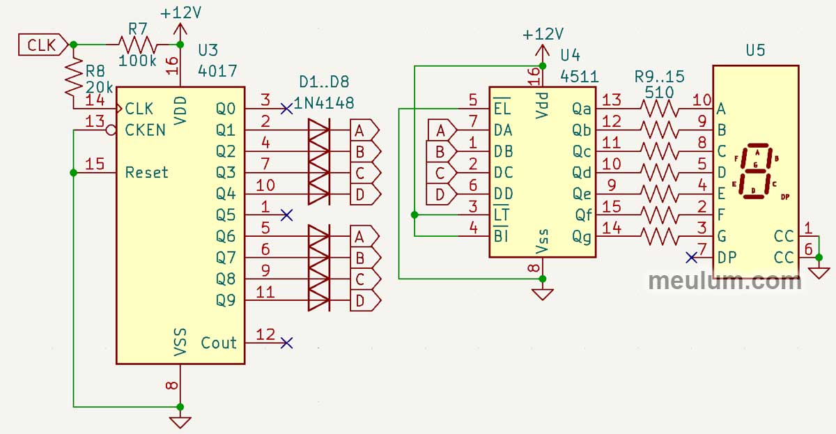
Outputs 0 and 5 of the 4017 are unused. Outputs 1 and 6 set bit A, 2 and 7 set bit B, 3 and 8 set bit C, and 4 and 9 set bit D on the 4511.
This creates a repeating binary sequence: 0000 - 0001 - 0010 - 0100 - 1000 - 0000 - 0001 - 0010 - 0100 - 1000, which corresponds to decimal digits 0 - 1 - 2 - 4 - 8 - 0 - 1 - 2 - 4 - 8.
The 4511 chip is configured for latched input, so the LED display instantly reflects the 4017’s current output.
Instead of simply displaying numbers, the Johnson counter 4017 can also send a programmed command sequence to an actuator and pause the process if overheating or another fault signal is detected.
Once the fault clears, the system resumes from its previous state rather than resetting. In automation, errors fall into two categories:
- Non-critical: The system resumes automatically after the issue is resolved
- Critical: Requires full system stop and human intervention
Overheating is usually non-critical, and today’s demo shows how an automatic pause lets a device cool before continuing operation.
Meanwhile, the technician can stay focused, but in real-world systems, every event is logged digitally.
Over time, analyzing these logs helps detect component wear and schedule maintenance, calibration, or replacement - improving uptime, reliability, and safety in automated systems.


