
In areas where people enter briefly from time to time, it doesn’t make sense to keep the lights on constantly. Today, we will assemble a circuit that activates lights for a short period when two conditions are met: a person is detected, and natural light from the window is insufficient.
This will allow comfortable use of a hallway, closet, or other utility room, while saving electricity and extending the light’s lifespan.
To detect a person’s presence, a pyroelectric motion sensor can be used. We have a separate article about it.
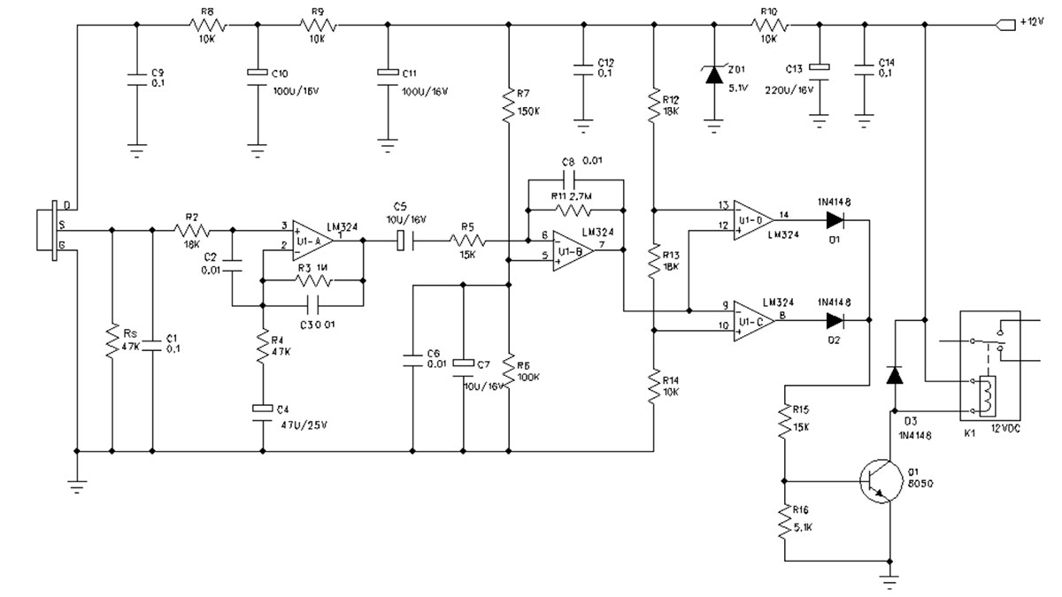
Processing signals from a passive infrared sensor requires a fairly complex amplifier with filters and comparators, or a specialized chip.
Interestingly, this chip, BISS0001, has all the features needed not only for an alarm sensor, but also for controlling hallway lights.
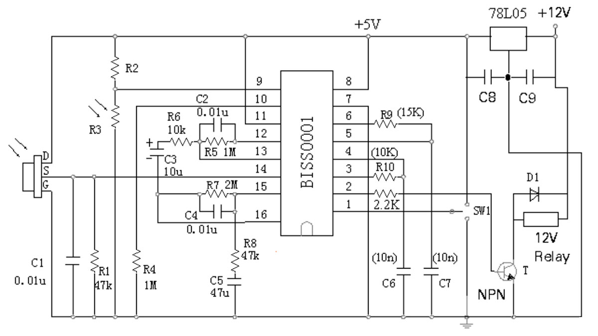
Resistor R10 and capacitor C6 determine the time the relay contacts remain closed when the sensor triggers, and resistor R2 sets the maximum illumination of the photoresistor R3 at which the light will still turn on.
In the upper position of switch SW1, the light will stay on as long as signals from the PIR sensor indicate a person’s presence. This is very handy for utility rooms where touching the switch is undesirable.
In the lower position of SW1, after the set time, the chip will turn off the relay and react to movement in the sensor’s range only after the time determined by resistor R9 and capacitor C7 has elapsed.
The lens of the pyroelectric sensor should be positioned in a specific place on the fixture or its control unit to cover the entire working area.

This is not always possible, but there are other ways to detect a person’s presence. The simplest is sound detection using a regular microphone. It works especially well in rooms with smooth, hard floors and echoing walls.
Today, I will assemble a device that reacts to the sound of footsteps or other noises if the photoresistor is sufficiently dimmed, using a single CD4011BE chip, one S9014 transistor, and one MCR100-6 thyristor.
It’s reasonable to start examining the circuit from the power supply unit. Our light fixture is powered by AC from a 12-volt transformer winding.
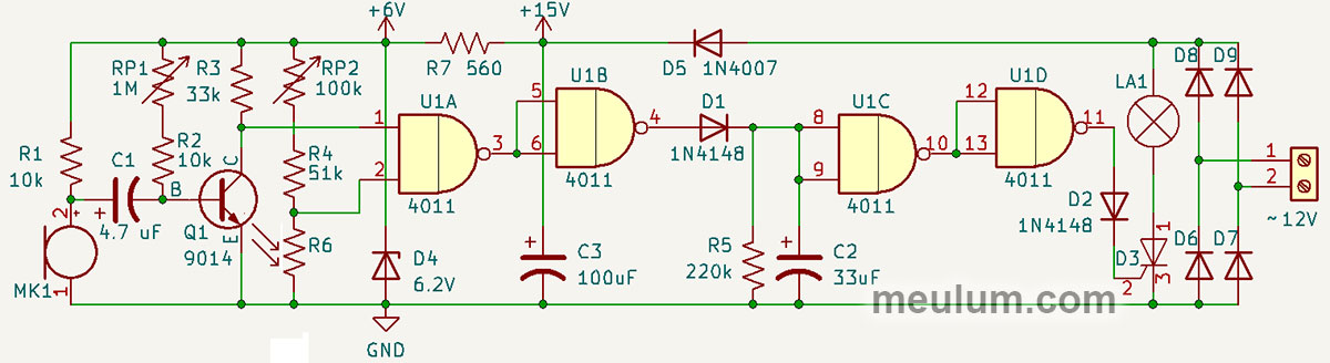
Diodes D6..D9 form a full-wave bridge rectifier, converting 12V RMS AC to pulsating DC with an amplitude slightly above 16 volts due to the voltage drop across silicon diodes 1N4007.

Through D5, this pulsating voltage reaches the filter capacitor C3, smoothing it into steady DC.
You might ask, why another diode in the power circuit? Couldn’t we just connect the electrolytic capacitor C3 directly to the rectifier’s output?
In this case, the extra diode D5 is necessary because the solid-state relay that turns on the lamp L1 must be powered by a pulsating current.
The silicon-controlled rectifier (SCR) D3 opens when a positive trigger pulse relative to the cathode is applied to its gate and remains open until the anode-to-cathode current falls below the holding current.

In other words, in the circuit with the lamp, an open thyristor stays open until power is cut. Pulsating current "turns off" one hundred times per second.
Therefore, the lamp will stay lit as long as a positive voltage relative to the cathode is present at the SCR’s gate, sufficient to create a trigger pulse, and will not light if this positive voltage is absent.
The MCR100-6 thyristor requires less than 200 microamperes of gate current to open. Any logic gate will supply this current easily. Essentially, it becomes a solid-state relay controlled by logic-level voltage from gate U1D.
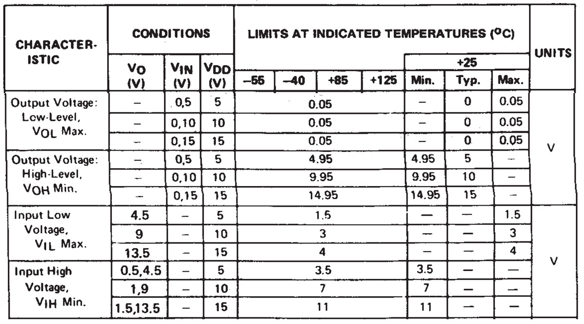
CD4011BE is a chip built with CMOS technology. Its outputs provide a low logic level voltage of no more than 50 millivolts, which is an order of magnitude below the MCR100-6 trigger voltage. For even greater reliability, diode D2 is included, which drops about 700 millivolts.
And diode D1, together with capacitor C2 and resistor R5, forms a time relay, or a retriggerable monostable multivibrator. It works as follows.
While a high logic level is present at U1B’s output, C2 charges through D1 and remains charged. When the logic one at U1B’s output disappears, C2 starts discharging through R5.
NAND gates U1B, U1C, and U1D act as logical inverters since both inputs of each are connected in parallel. Sequentially connected U1C and U1D perform a double inversion, forming a logical buffer.
Thus, a logic zero at U1B’s input lights a 12-volt one-watt incandescent bulb, LA1, and keeps it lit.
When U1B’s input, i.e., U1A’s output, goes to logic one, the bulb continues to light until C2 discharges through R5 to the CD4011BE chip’s logic zero voltage.
The chip and microphone amplifier are powered by 6 volts from a shunt parametric stabilizer on a Zener diode, with operating current limited by resistor R7.
To have logic zero on U1A’s output, high voltage levels are needed on both inputs of the NAND gate.
The resistance of photoresistor R6 decreases with increased illumination. Potentiometer RP2 can be adjusted to set the light level at which a logic one will be on U1A’s lower input.
Potentiometer RP1 sets the base bias current of transistor Q1 so that if the microphone MK1 signal is insufficient, a logic zero will be on U1A’s upper input.
This adjusts the sensitivity of the noise and illumination sensors, controlling the smart light on logic gates. You can see how this circuit works in the video.
This is a simple and reliable circuit solution, built entirely with widely available components found in any electronics store. And this automatic light fixture works just as well as a similar device with a PIR motion sensor and specialized chip.


