Integrated circuits like the HX711 contain signal amplifiers and analog-to-digital converters (ADCs) that allow you to connect a load cell to any microcontroller without requiring numerous additional components.
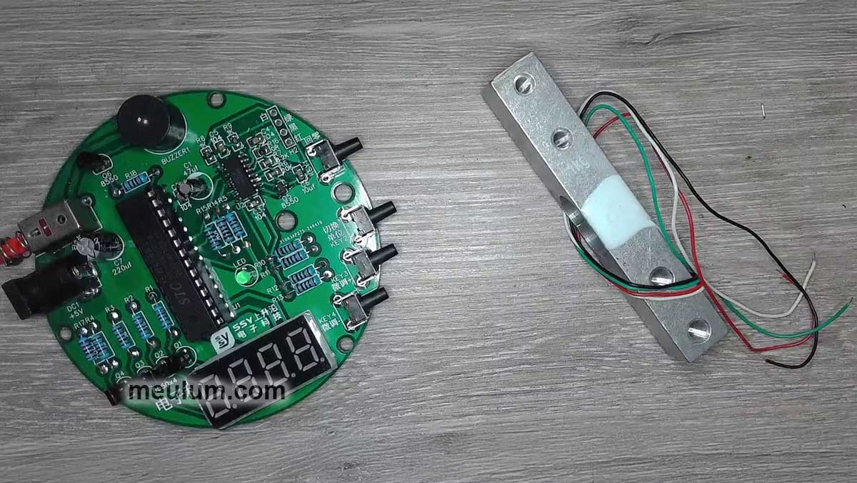
Today, we'll assemble simple electronic scales using a bending beam load cell. This sensor's operating principle is quite straightforward.
A very thin wire, folded multiple times, or a flexible printed circuit board with extremely thin metal foil traces is bonded to the surface of an elastic element that experiences tension or compression.

By Daraceleste - Own work, CC BY-SA 4.0, https://commons.wikimedia.org/w/index.php?curid=80883332
In actual load cells, these sensitive resistors are concealed beneath a layer of elastic potting compound.
When the aluminum beam bends under a suspended load, the upper resistors stretch while the lower ones compress.

We know that a conductor's resistance equals the resistivity of its material multiplied by its length and divided by its cross-sectional area. If you stretch a wire, its resistance increases; if you compress it lengthwise, the resistance decreases.
Since all the sensitive resistors in the load cell are made of the same metal, their temperature coefficient of resistance remains identical.
This means the ratio of their resistances doesn't depend on temperature! It depends solely on the radius of curvature of the resistors' bend.
The more weight suspended from the beam, the more it bends, stretching the upper resistors and compressing the lower ones. Thus, we obtain a force-to-resistance transducer.
The load cell uses a total of four resistors or four resistor groups connected in a Wheatstone bridge configuration.
A constant excitation voltage is applied to the vertical terminals of the Wheatstone bridge, while the output signal is taken from the horizontal terminals.
The bending beam load cell features markings that indicate the maximum allowable load mass and the direction in which the beam should bend.
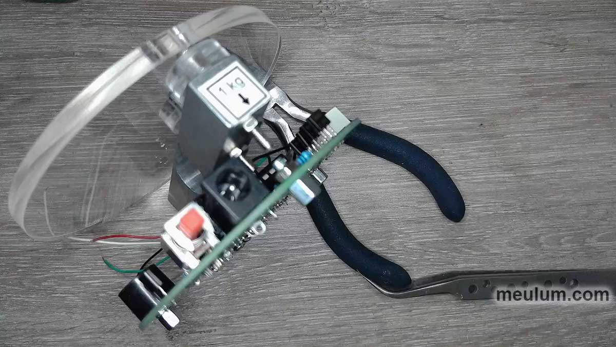
White plastic posts secure the fixed end of the beam to the scale base, which in our laboratory model is a printed circuit board.

The load platform attaches to the movable end of the beam using clear acrylic glass washers. This arrangement suspends the platform from the sensor beam above the scale base.
As you might expect, the ratio of the sensitive resistors' resistances changes only very slightly when the beam bends. Therefore, the Wheatstone bridge's output voltage is quite small.
Consequently, we need a precision low-noise amplifier. The HX711 chip contains exactly that.

The integrated circuit has two differential inputs and a multiplexer that determines which input's voltage will be amplified and digitized.
PGA stands for Programmable Gain Amplifier. The gain for Channel B is always 32, while Channel A can be set to one of two values: 64 or 128.
With a 5-volt supply, a gain of 128 corresponds to an input differential voltage range of ±20 millivolts. Accordingly, a gain of 64 provides a range of ±40 millivolts, while 32 gives ±80 millivolts.
By default, after a power-on reset, Channel A with 128x gain becomes active. Subsequently, channel and gain selection occurs through the number of clock pulses when reading the analog-to-digital conversion result via the serial interface.

The signal to begin reading ready data is the DOUT pin transitioning from high to low logic level. Then, 24 clock pulses are applied to PD_SCK to retrieve the data.
This process utilizes shift registers within the HX711 chip and in the microcontroller or logic circuit that processes the mass or force measurement results.
We have a separate article detailing how shift registers work and enable unlimited data transmission over just two wires - https://teardownit.com/posts/how-does-binary-logic-work-shift-registers

The 25th clock pulse returns DOUT to a high logic level until data from the next analog-to-digital conversion becomes ready.
If a 26th clock pulse is applied during the conversion period, the next conversion will be performed from input B with 32x gain.
If 27 pulses are sent, input A with 64x gain is selected. Sending fewer than 25 or more than 27 serial interface clock pulses is not permitted, as it may cause errors.
Between reading measurement results, the logic level on the PD_SCK pin must remain low.
The number of samples per second depends on the analog-to-digital converter's clock frequency. If the XI pin is grounded, the internal RC oscillator sets this frequency.
You can also connect a crystal resonator or external clock generator (through a 20 picofarad capacitor) to the XI and XO pins.
An amplitude of 150 millivolts suffices for ADC clocking. The waveform shape—whether square, sinusoidal, or other—doesn't matter. You can even connect directly to a microcontroller's crystal resonator.
The RATE pin sets the clock divider for analog-to-digital conversion. When using the internal clock generator, or external crystal/clock at 11.0592 MHz, a high logic level on RATE yields 80 samples per second, while a low level gives 10 SPS.
Another useful module built into the HX711 chip is the analog supply regulator. It's designed to maintain equal voltages on the VBG and VFB pins.

VBG is the output of the internal bandgap reference voltage, equal to 1.25 volts. This output is AC-grounded by a 0.1 microfarad capacitor, C3.
VFB is the feedback voltage input. With R1 = 20k and R2 = 8.2k, the voltage at the collector of transistor Q5, which powers the Wheatstone bridge, equals 1.25 × 28.2 ÷ 8.2 = 4.3 volts.
If we don't use the internal voltage regulator, VFB should be grounded, and capacitor C3 becomes unnecessary.
Here's an example procedure for reading ADC data from the HX711 chip:
sbit ADDO = P1^5;
sbit ADSK = P0^0;
unsigned long ReadCount(void){
 unsigned long Count;
 unsigned char i;
 ADDO=1;
 ADSK=0;
 Count=0;
 while(ADDO);
 for (i=0;i<24;i++){
 ADSK=1;
 Count=Count<<1;
 ADSK=0;
 if(ADDO) Count++;
 }
 ADSK=1;
 Count=Count^0x800000;
 ADSK=0;
 return(Count);
}
This demonstrates the operation of my homemade electronic scales:
Weight sensors find applications not only in kitchen and bathroom scales but also for remote monitoring of liquid levels in sealed tanks, honey in beehives, and many other uses.
They're also employed in museums to protect valuable exhibits, as we've often seen in films. Additionally, weight sensors are embedded in elevator floors to prevent overloading and have numerous other applications.
Now we understand how they work and can develop our own devices using them.


